- +91 - 9825062744
- G.I.D.C. Odhav, Ahmedabad - 382415 Gujarat, India.
- info@globeseal.com
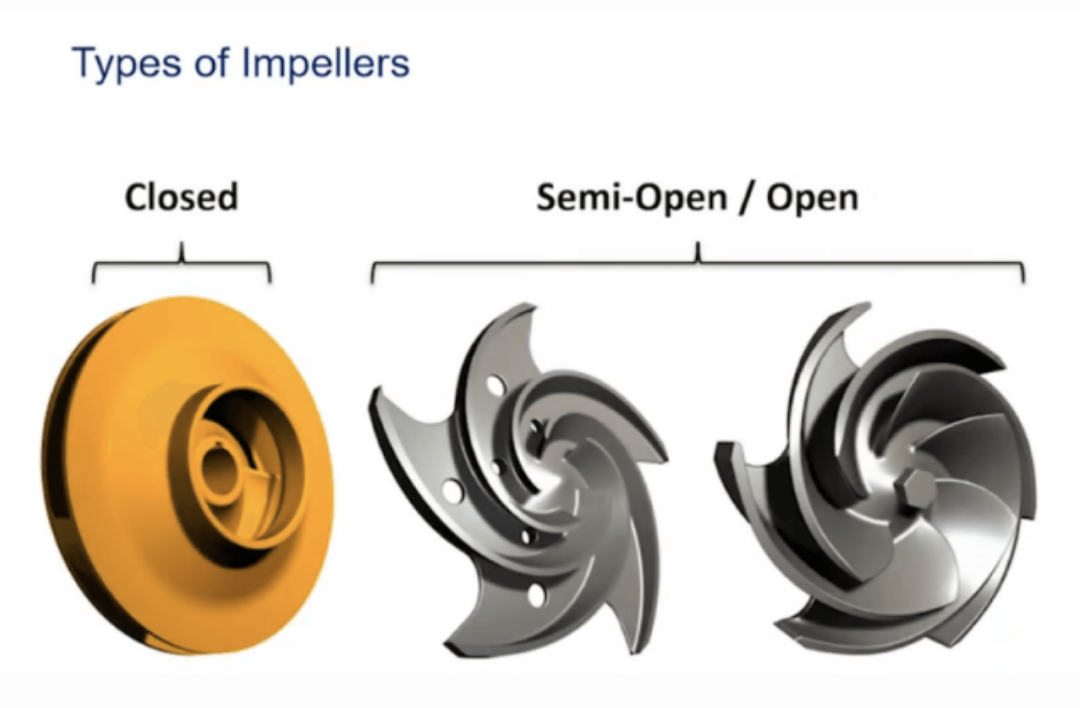
The impeller is the key component of a centrifugal pump . It consists of a series of curved vanes. These are normally sandwiched between two discs (an enclosed impeller). For fluids with entrained solids, an open or semi-open impeller (backed by a single disc) is preferred (Figure 1).
Fluid enters the impeller at its axis (the ‘eye’) and exits along the circumference between the vanes. The impeller, on the opposite side to the eye, is connected through a drive shaft to a motor and rotated at high speed (typically 500-5000rpm). The rotational motion of the impeller accelerates the fluid out through the impeller vanes into the pump casing.
There are two basic designs of pump casing: volute and diffuser. The purpose in both designs is to translate the fluid flow into a controlled discharge at pressure.
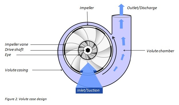
In a volute casing, the impeller is offset, effectively creating a curved funnel with an increasing cross-sectional area towards the pump outlet. This design causes the fluid pressure to increase towards the outlet (Figure 2).
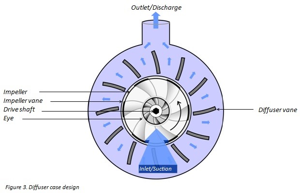
The same basic principle applies to diffuser designs. In this case, the fluid pressure increases as fluid is expelled between a set of stationary vanes surrounding the impeller (Figure 3). Diffuser designs can be tailored for specific applications and can therefore be more efficient. Volute cases are better suited to applications involving entrained solids or high viscosity fluids when it is advantageous to avoid the added constrictions of diffuser vanes. The asymmetry of the volute design can result in greater wear on the impeller and drive shaft.